ELECTRICAL
Electrical Diagram
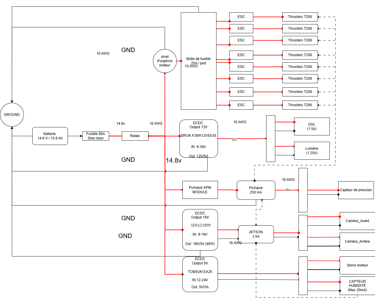
The electrical architecture is shown in the following diagram. There are three main power rails:
The 14.8 V rail, coming directly from the battery, powers the 8 thrusters, the DC-DC converters, and the Orange Cube
The 19 V rail powers the main computer (Jetson)
The 5 V rail powers the servo motors and the E-stop
The 12 V rail powers the lights and the Doppler Velocity Logger (DVL)
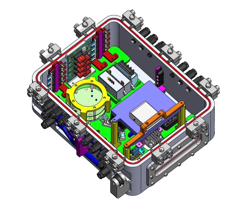
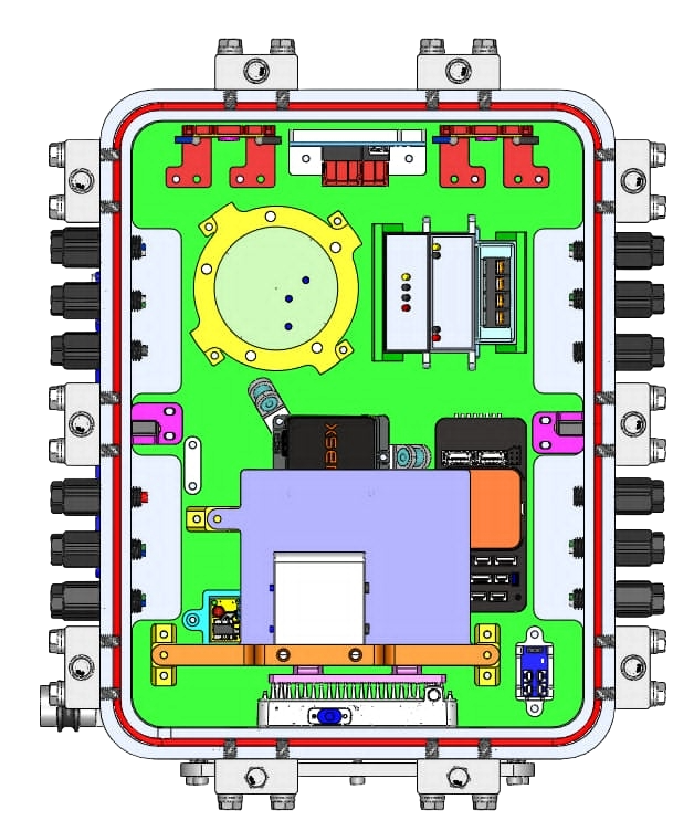
Electrical Assembly
The electrical assembly was meticulously designed. To reduce the weight of the submarine, the dimensions of the electrical enclosure were minimized as much as possible. Here are some key design considerations:
ESC connections routed along the walls to limit cable bulk in the center
DVL mounted at the bottom to allow heat dissipation through the aluminum enclosure
Visible LED indicators to monitor the robot’s status at all times
Vibration-proof mounting for the IMU

To limit the space occupied by components in the electrical enclosure, custom PCBs were designed. Here is the list of custom PCBs:
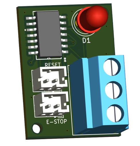
E-stop
Battery temperature sensors
Thruster power distribution with integrated fuses
These custom PCBs ensure that all competition requirements are met while optimizing space and integration.
CUSTOM PCBs